
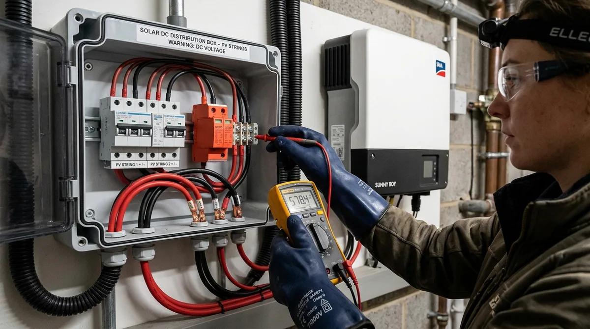
Across rooftop solar installations in Pakistan, extreme summer ambient temperatures routinely exceed 45 degrees Celsius, driving rooftop surface temperatures well past 68 degrees Celsius. Modern string inverters operate at DC string voltages between 350V and 850V DC, with open-circuit potentials frequently approaching 1,000V DC on cold winter mornings. To underbid competitors, untrained installers routinely cut corners by mounting standard 230V AC miniature circuit breakers (MCBs) inside DC Distribution Boxes (DCDBs) simply because AC breakers cost one-fourth the price of genuine 1,000V DC-rated switchgear. This single fraudulent shortcut is the leading cause of catastrophic rooftop electrical fires in residential and commercial solar installations across the country. In this technical guide, we break down the plasma physics of DC arcing, the internal electromagnetic mechanics of genuine DC isolators, and the mandatory standards required to keep high-voltage photovoltaic systems operating safely for decades.
Click to expand
The Arc Extinction Physics: Natural Zero-Crossing vs Continuous 3,000°C DC Plasma
To understand why an AC breaker self-destructs on a solar array, one must understand the fundamental difference in circuit physics between alternating current and direct current. In a standard 50 Hz AC grid (such as WAPDA), current and voltage alternate continuously, reversing polarity and passing through zero volts and zero amperes exactly 100 times every second. When an AC circuit breaker opens under a fault, a brief spark occurs across the parting copper contacts. Because the current naturally drops to zero every 10 milliseconds (at the zero-crossing), the electric arc is starved of energy, allowing the surrounding air to cool and regain its dielectric insulation strength. A standard mechanical air gap of just 3.5 to 5 millimeters is sufficient to extinguish an AC arc reliably.
When an installer mistakenly uses an AC breaker on a 600V or 1,000V DC solar string, the breaker may switch successfully once or twice under zero load. However, the moment a fault occurs or the switch is opened while full string current is flowing, the DC arc sustains itself across the narrow 4mm contact gap. The white-hot plasma column immediately melts the silver-plated copper contacts, vaporizes the brass terminals, and carbonizes the surrounding thermoplastic casing into a conductive graphite track. Within 30 to 90 seconds, the breaker casing melts, the distribution box ignites, and an uncontrollable structural fire spreads to roof shingles, waterproof membranes, or wooden ceiling joists.
Electrical Switchgear Comparison: AC Breaker vs Certified Photovoltaic DC MCB
Verified test standards under IEC 60947-2 (Circuit Breakers) and IEC 60947-3 (PV Disconnectors)
| Engineering Parameter | Standard AC Miniature Breaker (MCB) | Certified Solar DC Breaker (1000V PV) |
|---|---|---|
| Arc Quenching Mechanism | Relies strictly on natural 100Hz AC zero-crossings | Dual permanent magnetic blowout coils + 13-plate de-ion splitter chute |
| Rated Insulation Voltage (Ui) | 250V / 415V AC maximum | 1,000V to 1,200V DC continuous |
| Contact Separation Air Gap | 3.5mm to 5.0mm (single bridge) | 8.5mm to 12.0mm (multi-contact series breaking bridge) |
| Terminal Polarity Requirement | Bi-directional (non-polarized) | Strictly polarized (+ and - markings mandatory for magnetic deflection) |
| DC Short-Circuit Breaking Capacity (Icu) | Near 0 kA DC (melts and latches into sustained plasma arc) | 6.0 kA to 10.0 kA DC at 1,000V DC rating |
| Casing Fire Retardancy | Standard Nylon 66 / ABS (flammable under continuous arc) | Thermoset glass-reinforced polyester (UL94-V0 non-ignitable) |
Internal Anatomy: How Magnetic Blowout Coils Quench 1,000V DC Arcs
A certified photovoltaic DC circuit breaker is an advanced mechanical-electromagnetic device specifically engineered to conquer continuous direct-current plasma. Inside the breaker, permanent neodymium or high-coercivity ferrite magnets flank the stationary and movable contact pads. This configuration exploits the fundamental Lorentz force of electromagnetism: when an electrical arc forms, the charged moving electrons constitute an electric current vector traveling through an orthogonal magnetic field.
The resulting electromagnetic Lorentz force acts perpendicular to both the current flow and the magnetic flux lines. This force violently drives the plasma column laterally outward, away from the contact points and directly into a de-ionizing arc chute. The arc chute consists of 9 to 13 nickel-plated ferromagnetic steel splitter plates arranged like parallel cooling fins. As the plasma enters the chute, the conductive column is segmented into a dozen series micro-arcs. Each plate acts as an independent anode-cathode pair, raising the total arc voltage well above the solar array operating voltage while conducting extreme thermal energy away into the metallic heat sink. This cools the plasma below the ionization threshold of atmospheric gases, quenching the arc completely in less than 8 milliseconds.
The Series Arc Blindspot: Why Conventional Breakers Never Trip During an MC4 Fire
The most dangerous misconception among solar owners is believing that a circuit breaker will protect their home against all rooftop electrical faults. In reality, overcurrent circuit breakers only react to parallel faults—situations where positive and negative conductors short directly together, causing hundreds of amperes to flow through the breaker. However, over 80 percent of all photovoltaic rooftop fires are triggered by series arc faults, which occur along the continuous path of a single conductor.
A series arc typically begins at a poorly crimped MC4 connector, a corroded terminal, or a sun-baked cable splice. When thermal cycling (expanding in 45°C daytime heat and contracting at night) loosens a crimped metal pin, a micro-gap opens. High-voltage DC jumps this microscopic gap, establishing a series plasma arc. Because the arc itself introduces 15 to 40 Ohms of electrical resistance into the string loop, total circuit current actually decreases—for instance, dropping from 14.0 Amperes down to 8.5 Amperes.
Extreme Fire Danger
Series Arc Fault (MC4 Loose Crimp)
Current Drops — Breakers Completely Blind
Because the series arc adds electrical resistance, current falls below the breaker nominal rating (e.g. 8.5A on a 20A breaker). Standard MCBs and string fuses never trip. Meanwhile, 800W to 1,200W of localized thermal energy burns at 3,000°C, melting the MC4 shell and igniting roof underlayment.
Instant Solenoid Trip
Parallel Arc Fault (Conduit Short)
Current Spikes — Instant Electromagnetic Trip
Occurs when damaged insulation or rodent chewing allows positive and negative conductors to bridge directly. Massive fault current immediately energizes the magnetic trip coil inside the DC MCB, snapping contacts open and isolating the faulted string in under 15 milliseconds.
To detect and extinguish series arcs before a fire breaks out, modern solar systems require Arc-Fault Circuit Interrupter (AFCI) technology compliant with UL 1699B and IEC 63024. Tier 1 hybrid inverters (such as Huawei, Solis, and advanced Growatt/Knox units) incorporate high-speed digital signal processing (DSP) chips that continuously analyze high-frequency electrical noise (between 10 kHz and 100 kHz) characteristic of plasma sputtering. The moment an arc signature is identified, the inverter shuts down MPPT switching within 500 milliseconds, collapsing the current to zero and suffocating the arc.
Solar Cable Thermodynamics in 45°C Punjab Summer: Why 6mm² PV1-F Is Mandatory
A high-voltage DC protection system is only as reliable as the conductors linking the array to the distribution box. In Punjab, Pakistan, rooftop ambient air temperatures easily reach 45°C to 48°C in June and July. Inside closed PVC conduit exposed to direct unshaded solar irradiance on concrete or corrugated tin roofs, internal conduit temperatures routinely hit 68°C to 72°C.
Untrained installers frequently use standard 7/0.029 or 7/0.036 single-layer PVC domestic building wire. Standard PVC has a maximum temperature rating of only 70°C and degrades rapidly under ultraviolet (UV) solar radiation. Within 12 to 18 months, PVC sheathing turns brittle, cracks open, and allows moisture penetration, causing catastrophic ground faults. In sharp contrast, certified photovoltaic cable (EN 50618 H1Z2Z2-K / PV1-F) features double-layer cross-linked polyolefin (XLPO) insulation rated for 120°C conductor temperatures, halogen-free fire retardance, and a certified 25-year lifespan under intense UV exposure.
Furthermore, modern 550W to 650W bifacial solar modules generate maximum power currents (Imp) of 13.5A to 14.5A, with short-circuit currents (Isc) exceeding 15.5A when rear-side ground albedo reflection is factored in. When applying the standard 1.25 continuous design multiplier and thermal derating factors (0.71 at 68°C ambient conduit temperature), a standard 4.0mm² cable operates dangerously close to its absolute ampacity ceiling. Upgrading to 6.0mm² double-insulated tinned copper solar cable ensures minimal voltage drop (under 1.2% across a 30-meter run), eliminates conductor resistive heating, and safeguards inverter efficiency.
DC Surge Protection Devices (SPD): Guarding Against Induced Lightning Spikes
Modern solar inverters utilize sensitive power semiconductor devices, specifically Silicon Carbide (SiC) MOSFETs and Insulated-Gate Bipolar Transistors (IGBTs) within their Maximum Power Point Tracking (MPPT) boost stages. These electronic gates have maximum withstand voltages typically limited to 1,100V DC. During monsoon thunder showers across Pakistan, direct lightning strikes are rare, but nearby cloud-to-ground strikes produce massive electromagnetic pulse (EMP) fields that induce transient overvoltages of 6,000V to 20,000V along exposed rooftop DC cable loops.
A dedicated Class II / Type 2 DC Surge Protection Device (SPD) is mandatory on every MPPT input. The SPD contains high-capacity Metal Oxide Varistors (MOVs) matched to the maximum continuous operating voltage of the array (typically Uc = 1,000V DC). Under normal operation, the MOV presents near-infinite impedance. When an induced lightning spike exceeds 1,000V, the varistor transitions into a low-resistance conductor within 25 nanoseconds, shunting up to 40,000 Amperes (Imax) safely to earth before the spike reaches the inverter board.
Interactive Engineering Sizing Tool: Solar DC Breaker, String Voltage & Cable Sizer
Engineering Sizing Tool
Solar PV String Voltage, DC Breaker & Cable Sizing Calculator
Calculate winter open-circuit voltage, DC breaker ampacity, and cable voltage drop under extreme temperature swings
Calculate winter dawn string open-circuit voltage, DC breaker current rating, and cable loop voltage drop.
Input ParametersLive calculation
meters
30 meters
Physical cable run from rooftop PV array to indoor DC distribution box
Calculated Diagnostics
Winter Max String Voc (at 0°C)532.9 V DC
Recommended DC Breaker Rating25A DC MCB (1000V DC)
Cable Voltage Drop (One-Way 30m)2.58 V (0.6%)
Annual Resistive Energy Loss65 kWh/year
On a cold winter dawn (0°C), this string reaches 532.9V DC open-circuit. String voltage remains well within safe 1,000V DC inverter specifications.
Install a 25A DC MCB (1000V DC) polarized breaker. With 6mm² cable over a 30m run, your voltage drop is 0.6% (2.58V), wasting 65 kWh annually in resistive heating.
The Master Electrician Field Checklist: Safe Solar DC Installation
1. Certified 1,000V Polarized DC MCB
Verify DC Symbol and Terminal Markings
Check for the solid/dashed direct-current line symbol and 1,000V DC rating. Ensure positive string lead enters (+) terminal and negative string lead enters (-) terminal to direct magnetic blowout correctly.
2. Dedicated Class II Type 2 DC SPD
Uc = 1000V DC with Mechanical Flag
Install a dedicated 1,000V DC surge arrester with 40kA discharge capacity. Verify the mechanical inspection window is solid green and ground lead is at least 16mm² copper.
3. Calibrated Ratchet MC4 Crimping
Never Use Hand Pliers or Hammer Punches
Always use a dedicated ratchet crimping tool calibrated for solar pins. A cold-welded crimp guarantees zero micro-gaps, preventing 3,000°C series arcs under thermal expansion.
4. 6.0mm² Double-Insulated XLPO Cable
UV Resistant & 120°C Thermal Rating
Run genuine EN 50618 H1Z2Z2-K tinned copper cable inside UV-resistant conduit. Keep positive and negative conductors close together in the same conduit to eliminate inductive loop antenna hazards.
Topics & Tags:#solar dc breaker#ac breaker vs dc breaker#1000v dc isolator#solar arc fault#dc surge protector#mianwali solar#solar cable 6mm#afci protection#dc distribution box
Further Technical Reading
View allRelated Articles & Guides
Solar & Battery
12 min read
1000V DC Solar Disconnect Breakers vs AC MCBs: Arc Quenching Explained
Read Guide
Solar & Battery
8 min read
Calculate Home Load for Solar and UPS: The Master Electrician’s Guide
Read Guide
Fans & Motors
9 min read
Capacitor Sizing for Ceiling Fans: Microfarad Rating vs Winding Heat Rise
Read Guide